Computer Interface for Vintage Icom Radios
OVERVIEW:
Computer interfacing to ham radios
is common place now, but this has not always been the case. Several vintage
Icom radios provided for interfacing to computers. To my knowledge, the first
amateur radio to accommodate computer interfacing was the Icom IC-211 in 1976.
This was 5 years before the first IBM PC even existed for sale! Icom used the
same 24 pin accessory connector from at least 1976 to the mid-1980s. Many of
those supported computer control, and my interface works on most, if not all of
them.
Here is a list of the Icom radios
the interface will support. Not all of them have been tested because I have not
had access to a few. The interfacing standards have been incomplete, but I have
done my best and I believe all radios should work.
|
Radio |
Type |
Level
Translation Required? |
Startup
Freq (MHz) |
Verified
Operation |
YouTube
Video |
|
720A |
1 |
No |
14.275 |
YES |
https://www.youtube.com/watch?v=pMKQQLi5oME https://www.youtube.com/watch?v=v7thTKffiJo |
|
551 |
2 |
Yes |
52.525 |
||
|
560 |
2 |
Yes |
52.525 |
||
|
251 |
3 |
Yes |
146.520 |
YES |
|
|
260 |
3 |
Yes |
146.520 |
||
|
451 |
4 |
Yes |
446.000 |
||
|
701 |
5 |
No |
14.275 |
YES |
|
|
211 |
6 |
No |
146.520 |
YES |
|
|
245 |
6 |
No |
146.520 |
||
|
255 |
7 |
Yes |
146.520 |
Yes |
Table 1. Vintage Icom Radios that
the interface accommodates.
Unlike
today’s radios that use serial ports and USB (and even Ethernet), these radios
used a parallel sort of communication. This needs to be converted to something
modern computers can use, and that is the purpose of the interface. I got my
Icom 720A back in the early 1980s. It was my first "modern" HF radio.
Back then computer control was not even thought of by me. It would have been in
DOS and microcontrollers were not yet common in the hobbyist toolkit. I finally
decided to look into the idea of trying the interface after I had built a
similar interface for my much more modern Yaseu
FT-736R. At least it had a serial port. If you look at Ham Radio Deluxe (HRD),
these old radios are not even close to being supported, but I wanted to use Ham
Radio Deluxe. I decided to build an emulator that would pretend to be a radio
that HRD thought it was talking to. The emulator would take the data from the
HRD commands and convert them to what the actual radio needed to perform the
same function. It worked very well. I made a YouTube video showing it connected
to my 720A, and I got a lot of feedback, including many requests from people
wanting one. At that point, an accidental product was born. After I made the
720A interface, I had people ask me about the other support for the other
vintage Icoms. I discovered that the other radios had
different interfaces standards, some even used different voltages, and one of
them even needed an analog output. They all used the same 24 pin accessory
connector and managed to use the same pins, even with radically different
communications protocols.
I designed a circuit that I thought would
work on all of them, and I made the code so that the type of radio could be
selected by the user. I have laid out the circuit on a double-sided PCB that I
make available, as well as the programmed microcontroller. I also make a
separate daughter board for the radios that run on a 9V processor and need
level translation. The remaining parts must be acquired by the builder. A parts
list is provided below. I have tested the additional radios as they have become
available. All radios support the frequency control
and the PTT function. The 720A also supports mode selection. The 720A was the
only radio that provided remote control of mode selection. Three methods are
provided to interface to HRD. A regular serial (RS-232) connection, USB, or the
Icom CI-V interface are all supported. There is a jumper on the PCB provided to
select between RS-232 and USB. The hardware can be installed for both, but only
one can be used at any given time.
CIRCUIT DESCRIPTION:
The schematic for the interface is shown below in Figure 1. The
NAND gate is used to split the single wire CI-V signal into separate TX and RX
signals. This was needed to make the signals compatible with the output of the
RS-232 chip (IC1) as well as the USB chip (IC5). Whatever communication method
is used, the signals end up at pins 10 and 12 of the PIC (U1) as 5V serial
signals. The I/O pins to the right of the PIC in the schematic all begin with
the letter “M”. This denotes the pin number used on the 24 pin Molex connector.
IC4 is an op amp that is used to provide the analog signal that is used only on
the IC-701 for band switching. LED1 is mounted on the board and is an LED that
is used for troubleshooting. It’s ON/OFF state toggles as packets are received
from HRD. It is also used to verify configuration of the chip, which will be
discussed below. R6 is used for a power indicator LED should the PCB be mounted
in an enclosure. The board is powered by 12V that is supplied from the radio on
pin “M2”. If it is desired to put a power switch on the interface, the 12V from
“M2” should be interrupted with the switch. Q2 drives pin “M3” which is used
for PTT. Pads DB2, DB3, and DB5 correspond to the pins on a DB9F
connector for use with RS-232. Pad CIV1 is the center connector and CIV2 is the
shield on a 1/8 inch connector used on Icom CI-V interfaces. The USB Pads
correspond to the 4 signals on a standard USB interface.
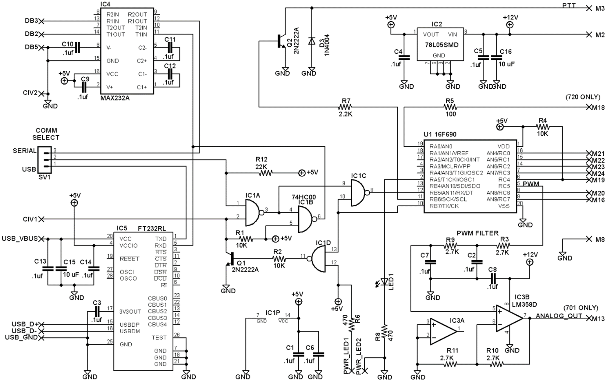
Figure 1. Schematic for the
Vintage Icom Interface
CONSTRUCTION:
The top and bottom layers of the PCB are shown in Figure 2. All
parts are surface mount except the processor, LED, 2 transistors, jumper block,
and the diode. The processor is a DIP chip so that it can be reprogrammed if an
important revision occurs. Larger SMD parts were used to make construction
easier for the home builder, except the USB chip (IC5). This chip was only
available in a smaller pitch package. All other components are 1206 packages or
50 mil spacing ICs. Because of the variety of radios supported, construction is
not the same for all boards. Differences are outlined in Table 1. If using the
USB chip, an associated driver is required for your Windows computer. Most
newer operating systems will find the driver automatically. If yours does not,
the driver is available from the FTDI website at http://www.ftdichip.com .
An IC socket is highly recommended for U1. A USB connector was not
used because it was decided to leave that to the builder and their individual
tastes. Whatever you use, make sure your USB connections are very short. Make
certain that you get the MAX232A that uses .1 uF caps
instead of the one that uses 1 uF caps. LED1 is an
off-board indicator that can be mounted on the face of whatever enclosure this
board is mounted in. In all cases for IC placement, the reference designator on
the PCB is on the side closest to pin 1 of the IC package. The jumper header
SV1 can be eliminated and a hardwire implemented if only RS-232 or USB is used.
The SV1 pads can be left open if only CI-V communication is used.
This is not a project for beginners and I will not hold your hand.
Undertake this project at your own risk. The microprocessors used in these old
radios are irreplaceable and I will not be responsible for your errors. At a
minimum. Make sure the output of the voltage regulator is 5V before you plug in
the processor into the DIP socket and the interface into the radio. It is
recommended that that IC2, C4, C5, and C16 be installed first. Once these
components are installed, temporarily connect two wires to the M2 and M8 holes
and connect those to a 12V power supply and confirm the regulator output is +5V
|
Part |
Value |
Package |
Comment |
Digikey P/N |
|
|
|
|
|
|
|
C1,C4,C5,C6 |
.1uf |
1206 |
|
399-1249-1-ND |
|
C16 |
10 uF |
1206 |
|
587-1352-1-ND |
|
D3 |
1N4004 |
DO41-10 |
|
641-1311-1-ND |
|
IC1 |
74HC00 |
SO14 |
|
568-10105-1-ND |
|
IC2 |
78L05SMD |
SO08 |
|
497-1180-1-ND |
|
LED1 |
LED5MM |
5mm |
|
C566C-RFS-CT0W0BB2CT-ND |
|
Q1,Q2 |
2N2222A |
TO18 |
2N3904 first alternate. Observe pin out |
2N2222ACS-ND |
|
R1,R2,R4 |
10K |
1206 |
|
P10.0KFCT-ND |
|
R6,R8 |
470 |
1206 |
|
RMCF1206JT470RCT-ND |
|
R12 |
22K |
1206 |
|
P22KECT-ND |
|
R7 |
2.2K |
1206 |
|
RMCF1206JT2K20CT-ND |
|
SV1 |
jumper header |
.1" pitch |
Hardwire if only using USB or RS-232 only |
3M9448-ND |
|
jumper |
jumper |
|
Hardwire if only using USB or RS-232 only |
A26228-ND |
|
U1 |
16F690 |
DIP20 |
Programmed IC available from KA6BFB for $35
plus shipping |
N/A |
|
PCB |
|
|
Available from KA6BFB for $30 plus shipping |
N/A |
|
Molex Connector |
|
|
WM1219-ND |
|
|
Molex Pins |
|
|
WM3680CT-ND |
|
|
|
|
|
||
|
R5 |
100 |
1206 |
Populate only on IC-720A application |
P100ECT-ND |
|
|
|
|
||
|
IC4 |
MAX232A |
SO16 |
Populate only when using RS-232 |
MAX232ACSE+-ND |
|
C9,C10,C11,C12 |
.1uf |
1206 |
Populate only when using RS-232 |
399-1249-1-ND |
|
|
|
|
||
|
IC5 |
FT232RL |
SSOP28 |
Populate only when using USB |
768-1007-1-ND |
|
C3,C13,C14 |
.1uf |
1206 |
Populate only when using USB |
399-1249-1-ND |
|
C15 |
10 uF |
1206 |
Populate only when using USB |
587-1352-1-ND |
|
|
|
|
||
|
R3,R9,R10,R11 |
2.7K |
1206 |
Populate only on IC-701 application |
RMCF1206JT2K70CT-ND |
|
C2,C7,C8 |
.1uf |
1206 |
Populate only on IC-701 application |
399-1249-1-ND |
|
IC3 |
LM358D |
SO08 |
Populate only on IC-701 application |
497-1591-1-ND |
|
|
|
|
|
|
Table 2. Parts List
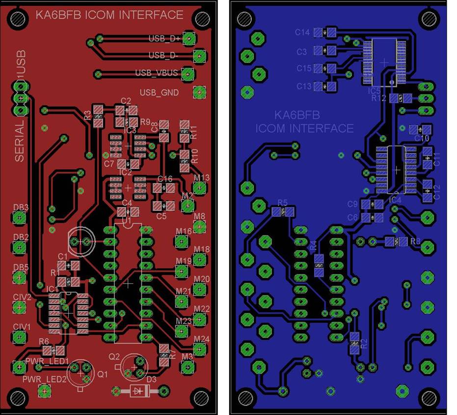
Figure 2. Top and bottom layers of the PCB.
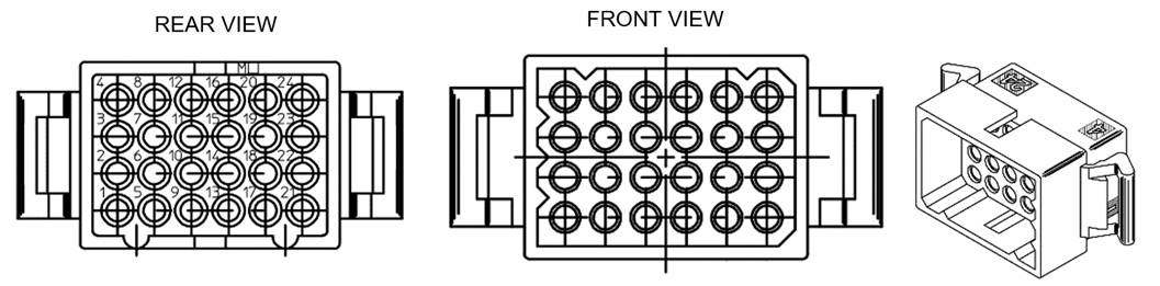
Figure 3. Front and back
mechanical views of 24 pin accessory connector
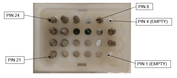
Figure 4. Front side of wired
24 pin accessory plug.
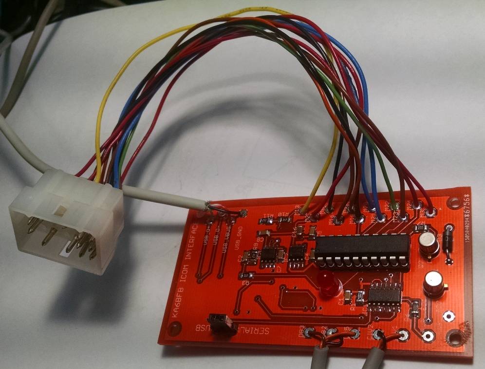
Figure 5. Finished prototype
interface used for validation.
If your radio is listed
on Table 1 as requiring a level translator, then your radio uses a 9V
processor, and the 5 Volt levels on the interface board need to be translated
to 9V. The translator information can be found here.
SETUP:
Prior to use, a onetime configuration of the microcontroller is
necessary. This is because you need to tell the microcontroller which radio you
are using. This configuration can be done through any of the interfaces,
RS-232, USB, or C-IV. Any terminal program can be used. In this example,
HyperTerminal will be used. All communications are at 9600 Baud 8N1. The
microcontroller is shipped with no particular radio selected. Plug the
accessory cable into the radio with the power off. Turn on the radio, then send
a character “S” (as in Setup) to the interface thru the terminal program. You
should get responses similar to the ones in Figure 6. If you do, congratulations
because this means most of the circuit is working. When prompted for the radio type, enter the
number that corresponds to your radio (1-7) from Table 1. If the radio
successfully received your radio type, the status LED on the PCB will illuminate
right after you enter your radio type. Simply power cycle the radio, and it
should come up to the default frequency shown in Table 1. If the display
changes to the correct default frequency from Table 1, then all of the
interface is working.
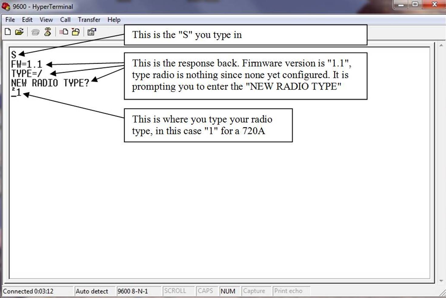
Figure 6. Setup dialog
in HyperTerminal.
OPERATION:
Close the terminal program and Start HRD and open the “connect” dialog.
The interface is emulating an Icom IC-7000 so we must tell HRD so. This is
shown in Figure 7, but your COM port will probably be different. Make sure the
speed and CI-V address match Figure 7 because HRD may try to change them.
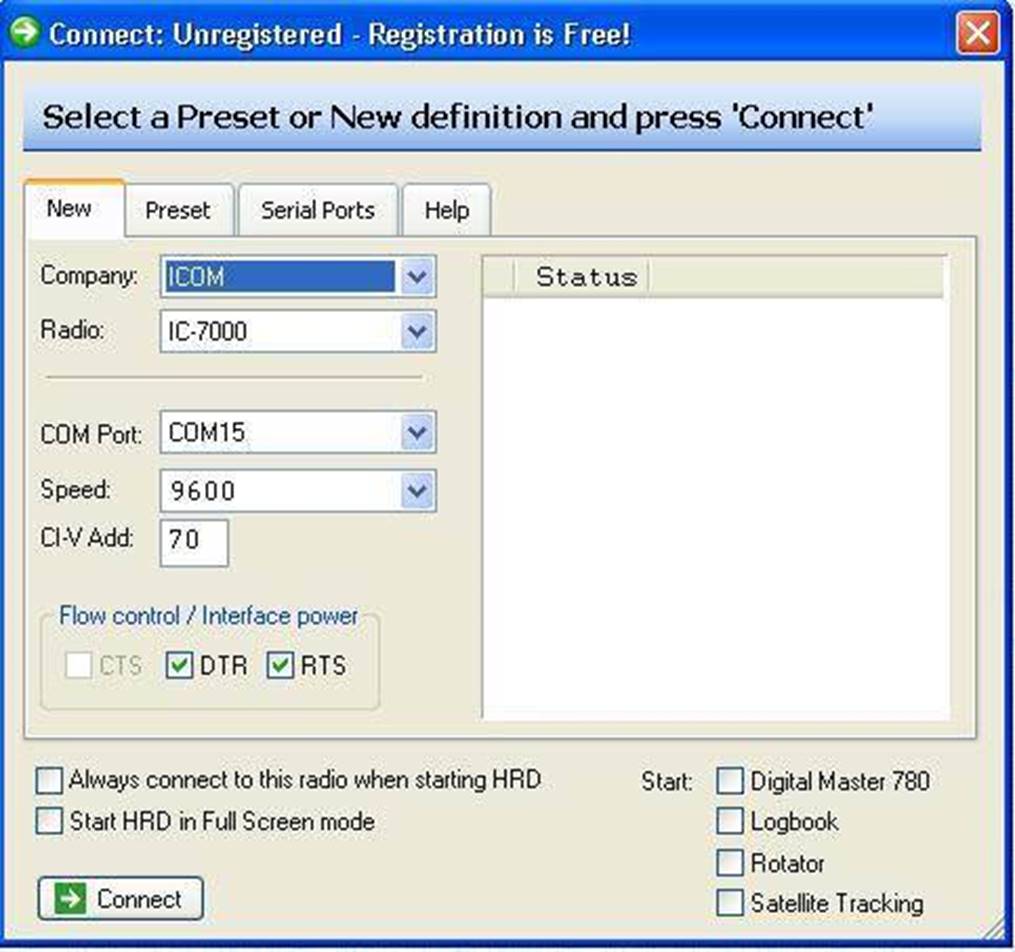
Figure
7. HRD COM Port setup
Once connected, your display will look similar to
the display shown in Figure 8. Since the Icom IC-7000 is crammed full of modern
wiz bang features, there will be many more buttons than shown in my customized
display. I suggest that you remove all the buttons except “PTT” and “MW”. If
you are using an Icom IC-720A, also leave the mode button as shown. I threw in
a wiz bang feature of my own. These radios did not come with memories, but I
have given them one. Once you are on any given frequency, if you press the “MW”
(Memory Write) button, that will become the default startup frequency when you
first turn on the radio. It will be stored in non-volatile memory inside the
microcontroller. On some radios, especially the 720A, the frequency controls on
the radio should not be used if the remote control circuitry has been
energized. If you do, the radio will lose sync and will need to be power
cycled. It is advisable to use the “lock” button on the radio so that the VFO
does not get accidentally bumped.
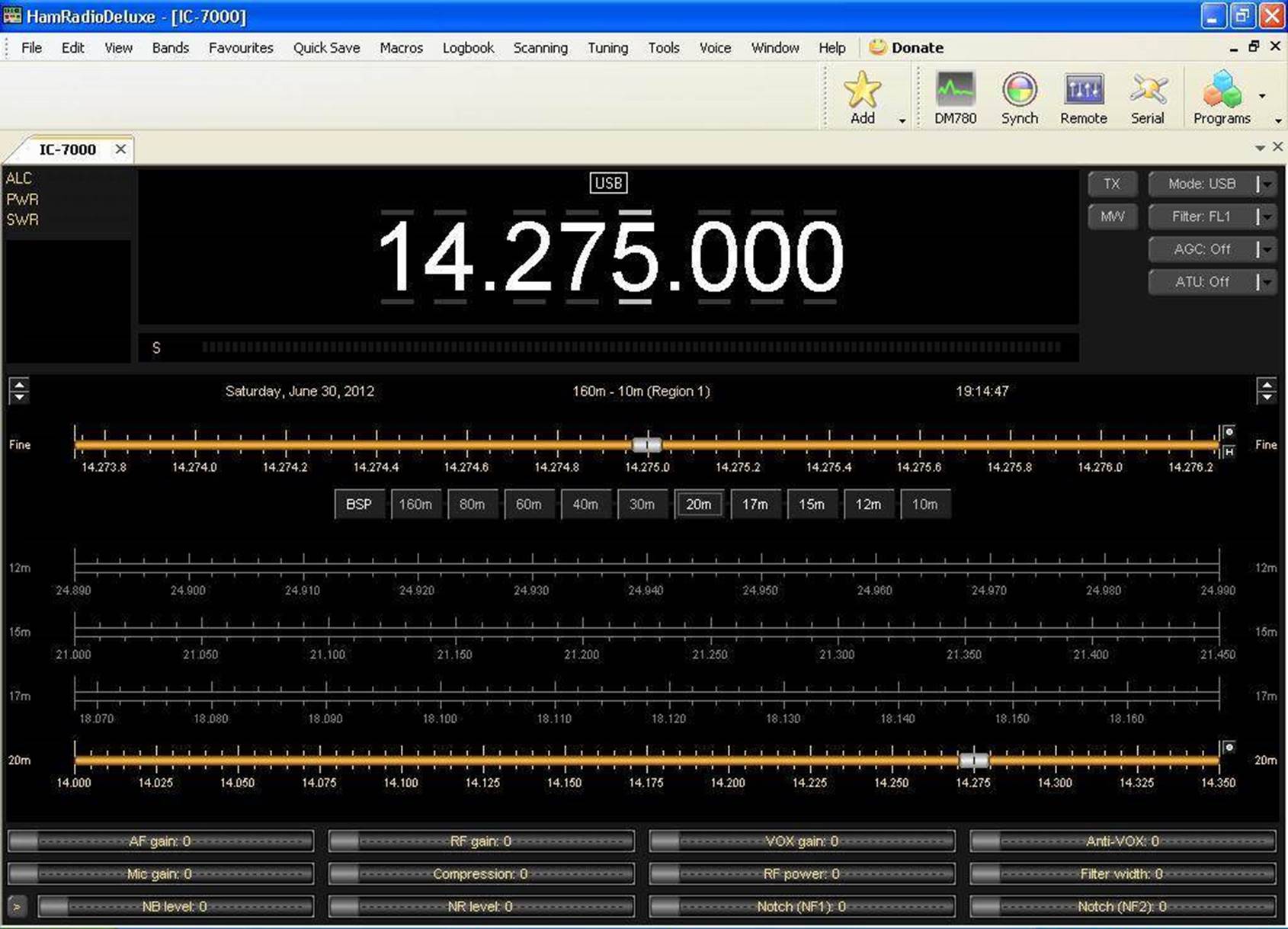
Figure 8. Ham Radio Deluxe display
Many thanks to Glen Williman, N2GW. I
could not get information on interfacing to the 211,245, and 701 anywhere. Even
Icom could not help me. I used Glens articles from QST and 73 and was able to
figure these radios out. Incidentally, if you try to use the supplemental
interface document from Icom for the other radios, be prepared for frustration.
Not all the radios match the specification. One day I may make a website to
post all of the interface information I have discovered.
73 Dave KA6BFB