Vintage Icom to
Ham Radio Deluxe
Interface Project
This project is result of the evolution of my original Icom 720A interface project which is also on this website. After I had finished that project and showed it on YouTube, I had many unexpected requests for a schematic and programmed chips. I designed a PCB and sold many chips. I was also asked if I could interface to other radios. I looked into this, and discovered that my original code and PCB could not simply be tweaked, but both needed a major overhaul to support all the radios that had pre-CI-V (AKA CAT CONTROL) capability. This is an understatement. Several of the radios use a protocol similar to the 720A, but the logic uses 9V levels instead of the 5V levels on the 720A. Three of the radios have a completely different protocol but use 5V. Then there is the IC-701 which actually requires an analog signal in addition to the digital circuitry.
Icom used the same 24 pin Molex connector for the accessory jack on many radios from 1976 to the mid-1980s. I have chosen to try to support all of the radios that had a parallel data based non-CI-V interface. Supported radios and their I/O connections are shown below in Table 4. So far, I have tested this new design on a few radios, as shown in Table 4. You can see videos of these working on my YouTube channel at http://www.youtube.com/user/TinkTron. I don’t possess the other radios. I am willing to make a deal with people that do have the other radios. I believe that I have written the code to work on all of the radios in Table 4, but I won’t claim it works until tested. If somebody is ever in my part of the world and has an unverified radio they would like to try, I will give them the chip for free if and when it works. I am not willing to take possession of radios thru mail or UPS. I don’t want the hassle of having something happen to the radio during transit. This must be done in person. I realize this might take a long time to finish.
In a nut shell, my code inside the microcontroller emulates an Icom IC-7000. Ham Radio Deluxe (HRD) believes that it is communicating with a ‘7000, and all of the data that it sends to the PIC microcontroller chip is then translated into commands that the vintage Icom radio understands to perform the same functions as commanded by HRD. All radios support the frequency control and PTT. The 720A also supports mode selection. The 720A was the only radio that provided remote control of mode selection. I have provided three methods to interface to HRD. A regular serial (RS-232) connection, USB, or the Icom CI-V interface are all supported. Because of the layout of the PCB, serial OR USB can be accommodated, but not both. You have to pick one.
The schematic for the interface is shown below in Figure 1. The NAND gate is used to split the single wire CI-V signal into separate TX and RX signals. This was needed to make the signals compatible with the output of the RS-232 chip (IC1) as well as the USB chip (IC5). Whatever communication method is used, the signals end up at pins 10 and 12 of the PIC (U1) as 5V serial signals. The I/O pins to the right of the PIC in the schematic all begin with the letter “M”. This denotes the pin number used on the 24 pin Molex connector. IC4 is an op amp that is used to provide the analog signal that is used only on the IC-701 for band switching. LED1 is mounted on the board and is an LED that is used for troubleshooting. It’s ON/OFF state toggles as packets are received from HRD. It is also used to verify configuration of the chip, which will be discussed below. R6 is used for a power indicator LED should the PCB be mounted in an enclosure. The board is powered by 12V that is supplied from the radio on pin “M2”. If it is desired to put a power switch on the interface, the 12V from “M2” should be interrupted with the switch. Q2 drives pin “M3” which is used for PTT.
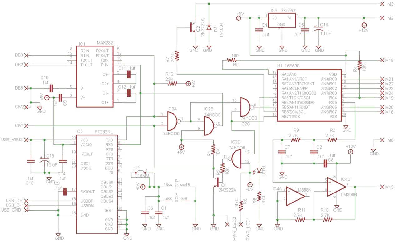
Figure 1. Schematic for the Vintage Icom to HRD interface
The parts layout is shown in Figure 2. I specifically laid out this board with just one copper side to make home construction simple. I managed to need only one jumper, of which I am especially proud. The jumper is J1, shown as a grey line in the Figure 2. All parts are thru hole parts and are mounted on the top of the board, with the exception of the USB chip (IC5) which is surface mount and mounted on the bottom (copper) side. Because of the variety of radios supported, construction is not the same for all boards. Differences are outlined in Table 2. This board and schematic were done in EAGLE. A hobby version of this software can be downloaded from the Cadsoft website at http://www.cadsoftusa.com . I will provide the CAD files for this project at the end of this page.
An IC socket is highly recommended for U1. The mating Molex plug for the accessory jack is Digikey P/N WM1219-ND and the pins are WM3680CT-ND. I did not choose a USB connector because I wanted to leave that to the builder and their individual tastes. Whatever you use, make sure your connection are very short. Here is a partial parts list.
The copper layer on the bottom of the board is shown in Figure 3. 100% scale artwork will be made available at the end of this page.
This is not a project for beginners and I will not hold your hand. Don’t take this on if you are a beginner at this sort of thing because my support will be minimal, if any. This project has turned into quite a time sink. Undertake this project at your own risk. Use common sense testing before you attach the finished project to your radio. The microprocessors used in these old radios are irreplaceable and I will not be responsible for your errors.
|
Part |
Value |
Comment |
|
C1,C2,C4,C5,C6,C7,C8 |
.1uf |
|
|
C9-C12 |
.1uf |
Populate only if using IC1 (serial) |
|
C3,C13,C14 |
.1uf |
Populate only if using IC5 (USB) |
|
C15 |
10 uF |
Populate only if using IC5 (USB) |
|
C16 |
10 uF |
|
|
D3 |
1N4004 |
|
|
IC1* |
MAX232A |
Use only for serial applications |
|
IC2 |
74HCO0 |
|
|
IC3 |
78L05Z |
|
|
IC4 |
LM358N |
Populate only on IC 701 |
|
IC5* |
FT232RL |
Use only for USB applications |
|
Q1,Q2 |
2N2222A |
|
|
R1,R2,R4 |
10K |
|
|
R3,R9,R10,R11 |
2.7K |
Populate only on IC-701 |
|
R5 |
100 |
Populate only on IC 720A |
|
R6,R8 |
470 |
|
|
R7 |
2.2K |
|
|
R12 |
22K |
|
|
U1 |
16F690 |
|
|
* NOTE Only populate Serial OR USB IC, not both. If USB chip is used, the proper USB driver for windows must be installed. It is available from the FTDI website at http://www.ftdichip.com |
||
|
PIC (U1) programmed for $35 plus shipping. Contact me via email. |
||
Table 2. Parts list for Vintage Icom to HRD Interface
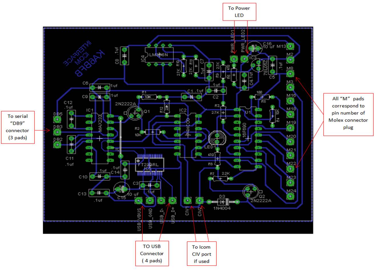
Figure 2. Parts placement for the PCB

Figure 3. Copper Layer for PCB
As I mentioned earlier, there were different protocols required for different radios. In general, the pins on the accessory jack that are used for interfacing are 13,16,18-24. Table 3 is a compilation of the different functions and voltage levels for each pin as it applies to each radio. An “X” means the pin is not used. The individual signals are in quotes in the table and reflect the usage in the individual user and service manuals for the radios. For example. “RT” is used in the 720A and means “remote”, while “8” is used on several radios and reflects the binary 8 pin in a parallel bus. It is not required to understand the meaning of this table, it is just shown for those that might be interested
|
|
|
PIN |
13 |
16 |
18 |
19 |
20 |
21 |
22 |
23 |
24 |
|||||||
|
|
RADIO |
720 720A |
X
|
I “DBC” |
5V |
I “RC” 5V |
O “DV” |
5V
|
I “RT” |
5V
|
I/O “1” |
5V
|
I/O “2” |
5V |
I/O “4” |
5V |
I/O “8” |
5V |
|
|
251,255,260 451,551,560 |
X
|
9V |
X
|
9V |
9V |
9V |
9V |
9V |
9V |
||||||||
|
|
701 |
I ANA LOG |
I “UDC”
|
I “CL”
|
I “E” 5V |
I “0” 5V |
I “1” 5V |
I “2” 5V |
I “4” 5V |
I “8” 5V |
||||||||
|
|
211,245 |
X
|
I “UDC” |
I “CL” |
||||||||||||||
Table 3. Pin functional list vs Radio for the pins on the accessory jack.
For all the radios above that require 9V logic, I have made a bidirectional level translator board that goes between the interface board and the radio. This board converts all signals that are necessary to be converted from 5V to 9V. As shown in the table, this is needed for the 251,255,260,451,551 and 560. As of this writing, this board has been successfully tested on a 251, and therefore should work on all of them. The schematic for this translator board is shown in Figure 4 and the parts placement is shown in Figure 5. The more than casual observer will notice that the copper is on the top side of the translator board. I have done this intentionally, as well as made the spacing and placement of the holes on the left side of the board line up perfectly with the interface board. This allows for, if the builder should choose to do so, placement of the translator board right on top of the interface board, resulting in one monolithic assembly. All that is required to attach them is a wire soldered thru the lined up holes. If this option is selected, the builder will probably want to mount the parts on the top side (copper side) of the board so that it matches the mounting of parts on the interface board. Of course the builder can choose to connect the two boards with wires and not stack them. In this case, it would be easier to mount the parts on the non-copper side.
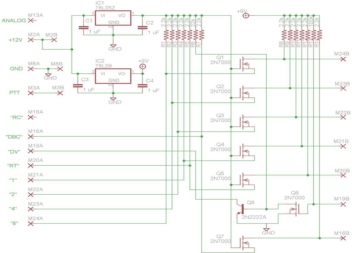
Figure 5. Schematic for translator board
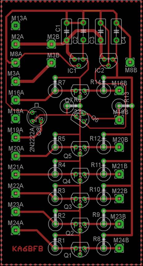
Figure 6. Parts placement for translator board
When you are ready to use the circuit, a onetime configuration of the microcontroller is necessary. This is because so many radios are supported that you need to tell the microcontroller which radio you are using. This configuration must be done either thru the USB or serial interface. Any terminal program can be used, I will show how to use Hyperterminal. All communications are at 9600 Baud 8N1. The microcontroller is shipped with no particular radio selected. When you first power up the radio, send a character “S” (as in Setup) to the interface thru the terminal program. When prompted, enter the one number that corresponds to your radio. If the radio successfully received your radio type, the status LED on the PCB will illuminate right after you enter your radio type. Simply power cycle the radio, and it should come up to the default frequency shown in Table 4. Figure 7 reflects the process in Hyperterminal
|
Radio |
Type |
Level Translator required? |
Default Freq (MHz) |
Verified Operation |
YouTube Video |
|
720A |
1 |
No |
14.275 |
YES |
|
|
551 |
2 |
Yes |
52.525 |
|
|
|
560 |
2 |
Yes |
52.525 |
|
|
|
251 |
3 |
Yes |
146.520 |
YES |
|
|
255 |
3 |
Yes |
146.520 |
|
|
|
260 |
3 |
Yes |
146.520 |
|
|
|
451 |
4 |
Yes |
446.000 |
|
|
|
701 |
5 |
No |
14.275 |
YES |
|
|
211 |
6 |
No |
146.520 |
YES |
|
|
245 |
6 |
No |
146.520 |
|
|
Table 4. Radio Types and default freqs.
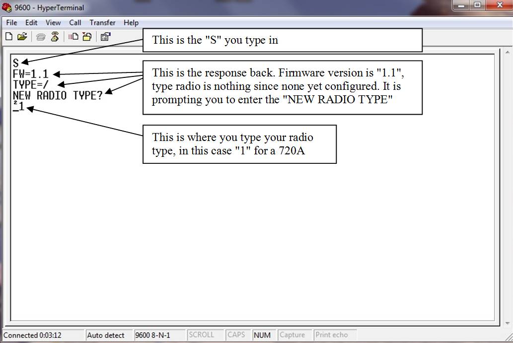
Figure 7. Setup dialog in Hyperterminal.
If you successfully configured the chip and power cycled the radio and it came up on the proper default frequency, you are ready to use HRD. Everything should be sunshine and lollipops from this point on. Start HRD and open the “connect” dialog. Remember, we are emulating an Icom IC-7000 so we must tell HRD so. This is shown in Figure 8, but your COM port will probably be different. Make sure the speed and CI-V address match Figure 8 because HRD may try to change them.
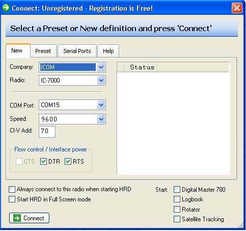
Figure 8. HRD COM Port setup
Once connected, your display will look similar to the display shown in Figure 9. Since the Icom IC-7000 is crammed full of modern wiz bang features, there will be many more button that shown in my customized display. I suggest that you remove all the buttons except “PTT” and “MW”. If you are using an Icom IC-720A, also leave the mode button as shown. I threw in a wiz bang feature of my own. These radios did not come with memories, but I have given them one. Once you are on any given frequency, if you press the “MW” (Memory Write) button, that will become the default startup frequency when you first turn on the radio. It will be stored in non-volatile memory inside the microcontroller. On some radios, especially the 720A, the frequency controls on the radio should not be used if the remote control circuitry has been energized. If you do, the radio will lose sync and will need to be power cycled. It is advisable to use the “lock” button on the radio so that the VFO does not get accidentally bumped.
Go ahead and enjoy the fruits of your labor.
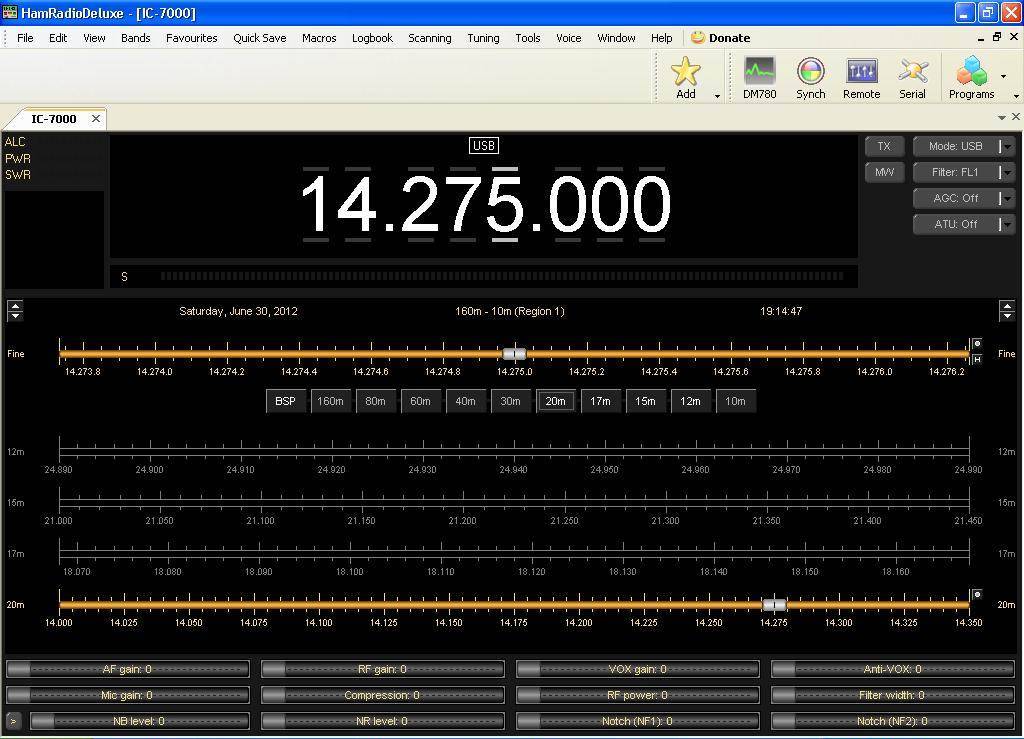
Figure 9. Ham Radio Deluxe display
CAD Files for PCBs can be downloaded here.
PCB Artwork at 100% scale can be downloaded here.
Many thanks to Glen Williman, N2GW. I could not get information on interfacing to the 211,245, and 701 anywhere. Even Icom could not help me. I used Glens articles from QST and 73 and was able to figure these radios out. Incidentally, if you try to use the supplemental interface document from Icom for the other radios, be prepared for frustration. Not all the radios match the specification. One day I may make a website to post all of the interface information I have discovered.
73 Dave KA6BFB