FT-847 Hardware Emulator for the FT-736R
Chuck, N6BIL, has implemented
a hardware version of the emulator project. All of the information needed to
make your own is available here. The PCB is available from the Batch PCB company
as shown below. The HEX file for programming the microcontroller is provided,
but you will have to arrange for the programming of the device yourself.
The finished product works
extremely well. Frequency corrections for Doppler shift can be made even while
transmitting. Once configured properly, operation is quite seamless. To use the
emulator, connect the emulator to a USB port and once it is recognized, it will
appear as a serial port on the computer. Go into HRD and select a new
connection to an FT-847 at the com port that corresponds to the emulator and at
a port speed of 4800. Press the connect button, and that’s it!
Most of the modes of the ‘847
work with the FT-736. The 847 was also an HF radio, so obviously the 736 will
not accommodate HF frequencies if you try that. The 736 can also support 220
MHz and 1.2 GHz, which the 847 could not. You can get 220 operation simply by
moving HRD to 220 MHz. 1.2 GHz operation is just a little more tricky. The 1.2
GHz band is 1240-1299.995 MHz. Since HRD in the 847 mode does not display this
range, a small trick has been incorporated. Drop the 1000 MHz digit and then go
to the frequency you want. For example, to go to 1247.660, go to 247.660 in
HRD.
Another item to look for
while in satellite mode is outlined in the 736 manual. The radio cannot
transmit and receive with the same band module. This may result in some
confusing situations if you accidentally try this. If you need to listen on 144
MHz and transmit on 440 MHz and the radio is already setup in the opposite
condition, you will run into the problem when you try to change one of the
bands because you can only change one frequency at a time and the radio will
reject your change because it seems like you want to have both transmit and
receive on the same band. The way to fix this is simple. Get out of the CAT
mode, and press the “REV” button and this reverses the bands associated with RX
and TX. Then reconnect with HRD and everything will be fine.
Chuck has made some videos
along the way for the project construction. They can be viewed on his youtube
site at
http://www.youtube.com/user/zdz801
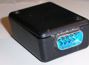
Here are a few pictures of
the completed project


This is Chuck’s
implementation (N6BIL)
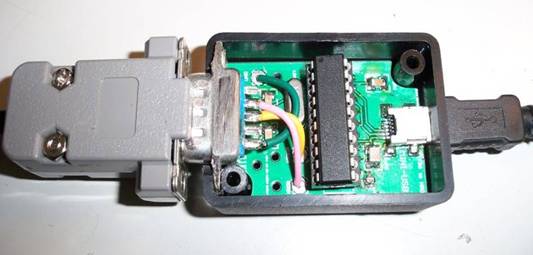
These two are my (KA6BFB) version using a DB9
connector.
Project Related Components
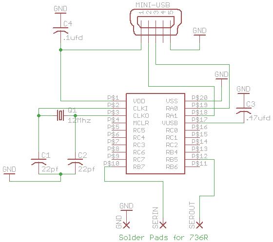
Schematic
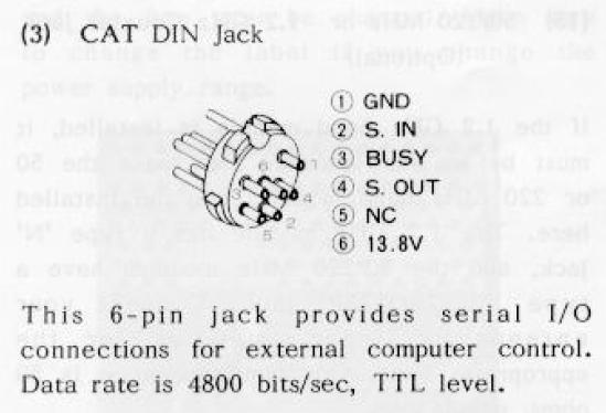
Connection to DIN Plug
As shown in the schematic
above, three wires are used to connect with the 736. One is ground and the
other two are signals. These signals are already at TTL levels, so no inversion
and level translation is required. A cable coming out of the box going directly
to the 6 pin DIN plug, or a DB9 intermediate connector can be used. Either way,
the following must ultimately happen
Pin 10 of the IC must connect
to Pin 2 of the DIN Connector
Pin 12 of the IC must connect
to Pin 4 of the DIN Connector
GND on the PCB must connect
to Pin 1 of the DIN connector
The image below is taken from
the 736 Manual and shows the pin out of the DIN connector.
Bill of Materials
|
Part |
Value |
Device |
Package |
Comment |
|
C1 |
22 pF |
Cap |
1206 |
|
|
C2 |
22 pF |
Cap |
1206 |
|
|
C3 |
.47 uF |
Cap |
1206 |
|
|
C4 |
.1 uF |
Cap |
1206 |
|
|
Q1 |
12 MHz |
|
HC49 |
Digikey P/N X1037-ND or equivalent |
|
U$1 |
PIC 18F14K50 |
DIP IC |
20 Pin DIP |
Digikey P/N PIC18F14K50-I/P-ND *** |
|
X1 |
MINI B USB |
Connector |
UX60-MB-5ST |
Digikey P/N H2959DKR-ND |
|
|
|
connector |
DIN 6 Pin |
DigiKey P/NCP-1060-ND |
|
BOX |
1551GBK |
Enclosure |
|
Digikey HM375-ND, Mouser 546-1551GBK, All Electronics 1551-GBK |
|
PCB |
|
|
|
N6BIL also has set up a project parts list at Mouser. The link is
https://www.mouser.com/ProjectManager/ProjectDetail.aspx?AccessID=5f0043a1df
N6BILs file describing driver selection here
Drivers
ZIP file containing driver files here
PCB Files
Eagle PCB Files here in case you want to make your own PCB. Otherwise simply purchase the finished PCB from Batch PCB as described in the Bill of Materials above
Software
All that is required is the HEX file to program the microcontroller. The HEX file is available here. The HEX file is all that is required to program the microcontroller.
If you want to look at all the original source code, it is available here